TALS (Tracking Automated Landing System) is an automatic landing system addressed to UAV applications. It is based on two independent and cooperative sections whose combined processing allows to feed attitude and position parameters to UAV autopilot.
The first section is based on a AHRS platform integrated with a GNSS/SBAS corrected signal (GPS,GLONASS,GALILEO or any other available satellite positioning system implementing augmentation). It is able to provide the UAV position with accuracy better than 3m.
The second section combines the information coming from a class of electronic sensors with information coming from real-time landing runway image processing, acquired through a properly aimed CMOS HD camera, or any other camera available on the UAV conforming to TALS specifications.
TALS may process real-time runway images in combination with preloaded images of the same runway or execute instant scanning of current runway image to search for landing reference points extracted from UAV maps data base. Reference points may be also received during the mission by remote command and control base, in case of change of final destination for landing. In this case, landing surface may be not necessarily an airport runway, provided that site for landing is identified with the proper reference points.
Both sections operate in automatic mode, creating a single common interface to UAV autopilot. The combined mode implemented in TALS reduces the bias error in calculation of UAV position and speed, allowing a significant increase in guidance parameters refresh frequency. TALS is able to recognize any kind of object present in the preloaded images used as a model; therefore landing scenario are possible also in absence of conventional runway and airfield ground light
The main key factor of TALS is that it’s a totally passive system as it works using runway and Airfield Ground Lighting (AGL) images as they are and/ or geodetic maps reference points . Thanks to TALS, safe landing of UAV will be always possible on runways not equipped with expensive navigation aids on the ground, such as ILS or MLS.
This peculiarity may result of crucial importance in applications where ILS or MLS , even if present on the runway, must be kept off due to security reasons. TALS may be therefore installed in UAV already equipped with ILS/MLS automatic landing systems, allowing the mission operator to decide where and when to use the most appropriate solution according to operational scenario.
Additional TALS advantages come from the invariance of reference images (with or without lights) by environmental conditions , while radio connection established between the ILS/MLS transmitter and UAV on board receiver may be subject to environmental and weather conditions. Ground reflections, in band interferences, presence of water or snow in the sensitive area of ILS/MLS beam, may in fact change the received reference path, producing wrong flight path indications for UAV autopilot.
TALS protects the value of UAV, and related payload, increasing safety during the landing, to be always considered as the most critical phase in the UAV mission. During final approach and landing , UAV may in fact be exposed to sudden changes of wind speed and direction (wind gust) creating serious troubles to attitude control of UAV. In such a scenario, TALS is able to provide accurate and real-time calculations for a better mitigation of turbulence effects.
TALS offers the following main performances during Approach and Landing phases:
- very accurate acquisition of current glide angle (real angle referenced to gravitational horizon, between UAV and runway touch down zone)
- calculation of :
- transversal bank referenced to runway axis;
- time to touch down;
- distance to runway threshold;
- UAV altitude over the runway;
- High updating frequency of autopilot flight parameters in the final phase of landing to increase the effectiveness of any UAV autopilot during turbulence management
- video signal of runway available to UAV remote pilot for supervisory purposes. Visual information may be integrated with markers to give the remote pilot additional information about runway and touch down zone position, current glide path angle and time to touch down.
Operational Phases
GNSS/SBAS (GPS,GLONASS) data are used by TALS to initially drive the UAV on the correct glide path angle and to align it to the runway axis.
Lock-on phase
Camera based auto-landing subsystem works in parallel with the GPS based one. The subsystem searches in the real-time acquired images for peculiar points of landing runway, extracting the information necessary to flight control, both in the horizontal and vertical plane. Such visual information will be fused with the other ones coming from other sensors (accelerometers, gyroscopes, altimeters, inclinometers) to feed in real time the UAV autopilot with requested parameters for approach and landing , with appropriate updating frequency and accuracy.
Tracking phase
Information from GNSS and camera based subsystem, are compared to check for data reliability. Frequency of UAV autopilot parameters updating is increased to 120 Hz.
Flare and Touch Down phase
 TALS sensors will provide at 120Hz UAV autopilot (and remote pilot) with following parameters:
- the UAV altitude over the runway (with 200 mm accuracy) attitude speed and position.
TALS operations will stop at the end of touch-down phase.
Technical Details
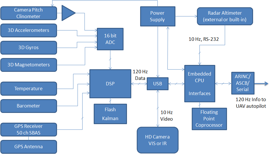
TALS diagram
The figure shows the general sensors configuration of TALS.
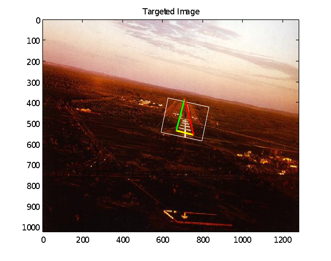
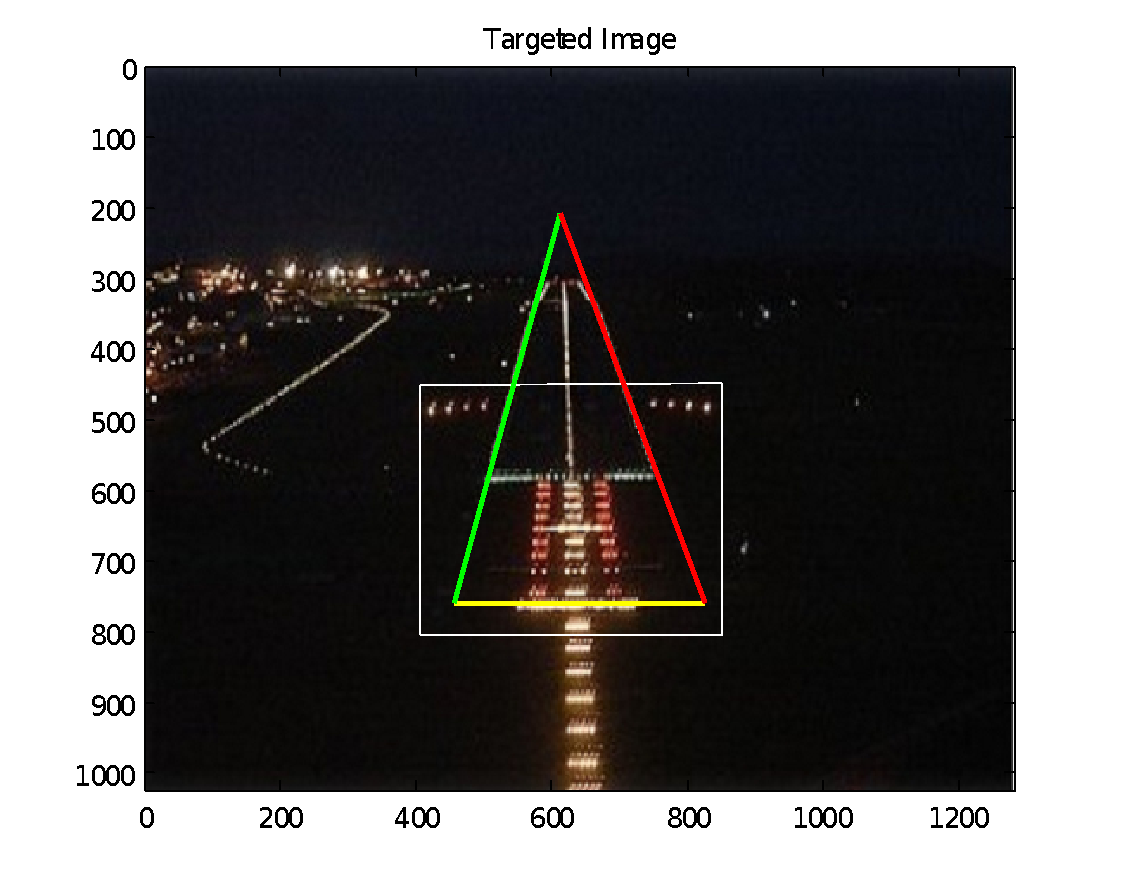
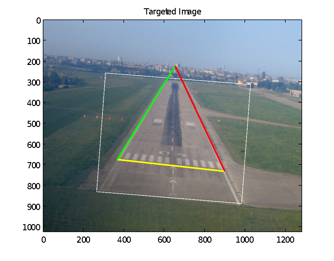
TALS basically works collecting images in realtime using a CMOS high definition, colour camera, operating in the visible spectrum , with a 30° Field of View (FOV) CMOS HD. Camera is a Gimbal type , to be installed (if not already present in UAV) under the nose of UAV. Landing runway recognition is based on detection of runway image peculiarities (features) and information given by the following AGL lighting systems:
- PAPI (Precision Approach Path Indicator) bars
- Approach Lighting Systems
- Runway Edge
- Runway Centreline
- Threshold and Threshold Wings
- Touch Down Zone (TDZ)
TALS needs a system data base loaded with two images of runway, shot at a close distance in day and night light, or loaded with geodetic references and refernce points of landing site according to UAV flight mission map. When available coordinates of TDZ lights , runway directions and altitude will be also stored in the system data-base.
TALS will properly work even in case of a poor GNSS/SBAS signal. Integration of visual information with data coming from sensors of AHRS platform allows for output of calculated values of UAV attitude and heading, including glide path angle and bank referenced to the runway axis. Data output frequency is maintained to 120 Hz even in case of loss of GNSS/SBAS signal. TALS can be therefore used as a back-up of UAV standard ILS based landing system drastically increasing autolanding capability of UAV.
During landing, video signal of runway may be available to UAV remote pilot for supervisory purposes. Visual information may be integrated with markers to give the remote pilot runway and touch down zone position, current glide path angle and time to touch down.
Below shows parameters and reference values calculated by TALS. Measurement of distance to runway threshold and transversal bank need GNSS/SBAS signal available.
- Current landing angle [deg]
Range 0-10 deg
Dynamic accuracy 0.08 deg - Time to touch-down [sec]
Accuracy: 0.5 sec - UAV altitude over the runway
Range 0-18 km
Accuracy: 0.2 m (at touch-down phase) - Distance to runway threshold
Range: 0 – 3.5 Nm
Accuracy: 2.5 m - Transversal bank referenced to runway axis [deg]
Range -10..10 deg - UAV roll, pitch, heading angles
Range -90..90 deg
Dynamic accuracy 1.0 deg - Information data rate
Up to 120 Hz - Video frames with markers output rate
10 Hz - UAV max. speed
2100 km/h - Max. dynamic measurement
4 g
TALS output signals may be adapted to every UAV command data port. System response time (120 Hz) allows for a prompt reaction to sudden changes (severe wind gust) of UAV attitude in the final phase of flight.
TALS runs on a SBC hosting the CPU, working memory and FPGA section to be devoted to high speed image processing algorithms. CPU collects data from sensors and CMOS HD camera to process and transfer parameters to UAV autopilot for landing. SBC provides for a communication interface to send/receive data to/from remote command and control base.
Processing unit will conform with standard MIL-STD-810F (shock, vibrations, temperature, humidity) and MIL-STD-461E for EMI/EMC.
TALS Performances
TALS performances have been compared with ILS ones through a simulation carried out applying Monte Carlo methodology and considering CESSNA 172 flight parameters. The purpose of simulation was to establish a reference for TALS performances in comparison with a known and certified system as ILS is worldwide.
The simulation model was based on aircraft equations and turbulence equations as they are set in international ICAO/FAA standards, assuming the presence of TALS or CAT II ILS system, with ILS errors within limits given in ICAO, Annex 10, Vol. I, Chapter 3.
Typical functions of a conventional autopilot have been included in the model, such as:
- internal control loops (for pitching, roll, yaw);
- basic functions (for en- route autopilot, altitude and speed)
- auto-landing function.
Operational parameters in the simulation model were set to:
- distance to landing point: 12200 m
- initial altitude range: 584 – 784 m
- initial misalignment (referenced to runway axis) range: -200..200 m
- turbulence zone extended from 9000 m to 400 m from touchdown point
- turbulence intensity range: 7 – 15 m/s
- glide path angle: 3°.