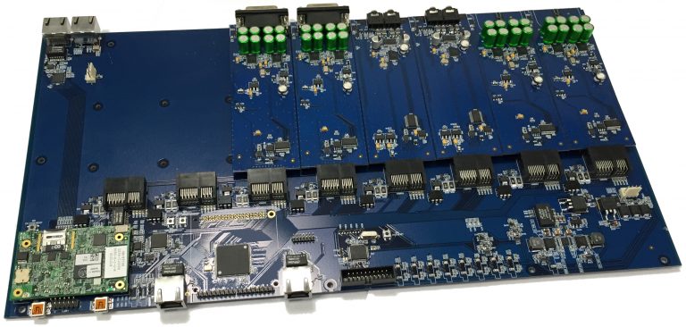
SIP / VoIP gateway is based on the carrier board with a digital bus, on which the bladed interface modules can be installed (see starting from the upper right corner). The photo shows 6 modules installed and two more free space for the left. Interface modules have connectors for external audio devices. In the lower left corner is shown embedded ARM / DSP computer module.
The gateway is designed to provide the functions of digital voice “Voice over IP” (VoIP) and switching media streams via SIP in the air traffic voice system controller – pilot, according to the requirements of the standard ED-136 and ED-137 A / B EUROCAE.
As assembling unit, the gateway contains the base plate, which is set up to 8 interface expansion cards to connect external audio devices. The gateway acts as CWP site, and as a Radio Gateway that is installed on the receiving – transmitting radio center. In this case, the gateway has only one type of interface expansion card, which provides E & M interface for the external radio receiver or transmitter. In this version, a radio gateway can connect up to 8 stations.
Gateway in CWP Site version
Interface cards have the following versions for connecting devices:
- headset, up to 2 units;
- gandset with PTT button, up to 2 units;
- microphone, up to 2 units;
- footswitch PTT, up to 2;
- external speakers, up to 8 pcs., 4 W each.
The gateway is connected to:
- external power supply + 24V;
- Remote Control and Managment System via Ethernet interface;
- external documentation system;
- redundant Ethernet interface to work in the VCS;
- Ethernet interface for communication with the CWP control panel.
Optionally in the CWP Site version SIP / VoIP gateway can be connected to the CWP control touch screen panel shown in the figure. This device is also developed by Primaria and shipped separately in different versions.
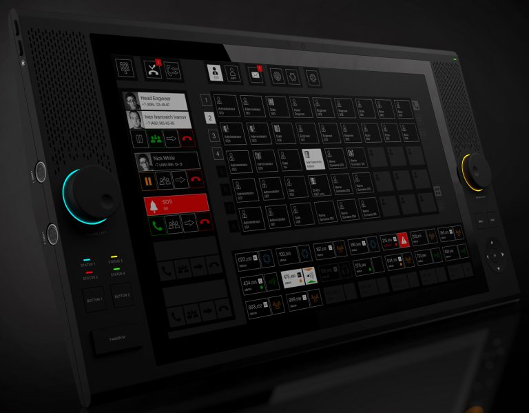
CWP touch screen control panel. It contains an open-frame display and capacitive touch glass. It can be equipped with additional built-in microphone and video camera. Contains a built-in two speakers and allows the connection of two redundant handsets
Gateway in Radio version: Radio Gateway
This version is used to connect non – VoIP, legacy radio stations. Radio gateway can also be supplied separately as expand card for a customer radio tranciever to conform ED-136, ED-137 specifications.
In this version Radio Gateway is installed in a rack with radio equipment together to ensure the following connections:
- Up to 8 full-duplex E&M radio interfaces (each interface provides PTT and SQ commands);
- external power + 24V;
- documentation system;
- redundant Ethernet interfaces for operation in the VCS.
Gateway Radio version and CWP Site version differs only by expansion interface cards set and software.
Common Gateway Features
Gateway uses an embedded ARM / DSP computer module. On the DSP heavy application is loaded, such as echo cancellation algorithms, speech codecs with audio compression and image processing with built-in video camera.
The gateway contains built Ethernet-Switch Moxa company EOM-104 for the fast detection of the Ethernet connection failure network and switching to a backup.
The gateway G.703 (E1) interface is provided for recording voice signals to an external digital recorder, the type of RJ-45 connector.
Interface expansion cards provide the following connections.
In the CWP SIte version:
- headset interface, variant 1: two Lemo-type connector for the headset with microphone and PTT button, the handset with the PTT button, microphone button PTT, PTT foot pedal. Microphone supply voltage from 5 to 12V;
- headset interface variant 2: one connector DSub type for simultaneous connection of a combination of 2 of the following devices: headset with microphone and PTT button, the handset with the PTT button, microphone button PTT, PTT foot pedal;
- speaker interface: two stereo connector type Jack Ø3.5 mm.
In the Radio Gateway version:
only one type expansion board: E&M module with one RJ-45 connector.
Electrical characteristics:
– Input impedance: 600/1200 ohms ± 20% at a frequency of 1 kHz;
– Output impedance: 600/1200 ohms ± 20% at a frequency of 1 kHz.
The value of the impedance is set with switches on the board.
Power is supplied from one of two independent DC power supplies with voltages from 18 to 32 V. The transition from one power source to another is provided without interruption in the work.